
Introduction
Rendering is the processor of generating an image from a 2D or 3D model by means of a computer program. It can be compared ot taking a photo of a scene in real life. Like how there are many cameras (e.g. DLSR, film, mirrorless) that each produce a different result, there are many rendering techniques that (e.g. polygon-based, scanline, radiosity, ray-tracing) that each have different tradeoffs. Today, we will be looking at ray-tracing.
In the real-world, photons collide with objects where it will be reflected or refracted while losing some energy along the way. Eventually, the photons end up in a camera’s image sensor which in turn produces an image. Ray-tracing aims to simulate the physics of real-world optics by tracing the path of rays to the camera. However, simulating every individual photon emitted from a light source is computationally expensive. In our simulation, we can use the principle of Helmholtz reciprocity to instead only shoot rays from the camera into the scene that will hit a light source. This, in combination with offloading computational load to GPUs have made ray-tracing one of the most popular rendering techniques to this day.
C# Script
Let’s leverage an existing game engine, Unity, to play with ray-tracing. This allows us access to features like an editor and asset manager to simplify our development.
In a new Unity project, I created a C# script. Here, we declare a couple of things:
A reference to our compute shader (technique to speed up computation, hence ‘compute’):
| |
Our frame as a Unity RenderTexture object (the underscore prefix ‘_’ is a
convention to indicate a private variable):
- This can be thought of as an individual frame that we will be writing to
| |
OnRenderImage(), Render(), and InitRenderTexture() functions that work
together to initiate ray-tracing calculations using a compute shader (that we
will soon write).
OnRenderImage() is a Unity built-in function called whenever an object is
being rendered. Here, it will serve as a post-processing step to initiate the
ray-tracing process and display the result on the screen.
| |
InitRenderTexture() creates _target if it doesn’t exist or if its dimensions
don’t match screen dimensions. We release the render texture if it already
exists, then create a new render texture using the
RenderTextureFormat.ARGBFloat format, which allows for high-precision
floating-point values for accurate ray-tracing calculations. enableRandomWrite
is set to true in order to enable the compute shader to write to the render
texture.
| |
Render() is responsible for ray-tracing and displaying the result. Notably,
it
- Calls
InitRenderTexture()to ensure that_targetis properly initialized - Sets
_targetto a parameter called “Result” in the compute shader - Calculates the number of thread groups needed for the compute shader based on screen dimensions
- Dispatches the compute shader, with a specified kernel index and number of thread groups in the x and y dimensions
- Copies the content of the
_targettexture to the destination, displaying the result on the screen
| |
Now, let’s initialize a Unity Camera object that will be attached to our main
camera.
- In Unity, the
Awake()method is called when a GameObject script is initialized. Here, the script retrieves the reference to the Camera component and assigns it to the private_cameravariable. - Now, in a separate method
SetShaderParameters(), we set two matrices in our compute shader._camera.cameraToWorldMatrixrepresents the transformation matrix that converts points from the camera’s local space to world space. This will be used to transform rays and objects into the appropriate coordinate system._camera.projectionMatrix.inverserepresents the inverse of the camera’s projection matrix. This will also be useful for ray-tracing calculations, like reconstructing the rays in world space from screen coordinates.
Note: These matrices are not matrices of pixels, but rather represent transformation and projection information to aid with manipulating points and vectors in 3D space.
| |
Compute Shader
Now, let’s move on to our compute shader.
Note: In HLSL, a function or variable declaration needs to appear before it is used.
To begin, we have:
| |
a preprocessor directive specific to compute shaders in HLSL. It designates
CSMain as the entry point or the main kernel function in the compute shader.
“#pragma” is a directive used to provide additinoal instructions to the compiler
or specific compiler optimizations. In our case, speaking to the GPU to run
multiple threads in parallel to speed up our ray-tracing computation.
In the context of parallel computing, “kernel” refers to a specific type fo
function that is execute on multiple threads or processing units, which we will
go into further depth later.
Next, we declare global variables that we passed into the compute shader from our C# script:
| |
Now, we create a ray struct which holds information about individual rays
(which we will add to later), and a function to easily create a Ray struct.
| |
Now, we use information from our camera matrices to calculate the origin and
direction of a Ray from the camera’s perspective to the world space.
float3 origin = mul(_CameraToWorld, float4(0.0f, 0.0f, 0.0f, 1.0f)).xyz;transforms the camera’s local origin to world space.- The following three lines takes the inverse of the camera’s perspective
projection matrix,
_CameraInverseProjectionand theuvvector, and converts it into a 3D vector in view space. Then, the vector is transformed from view space to world space, using the_CameraToWorldmatrix and is normalized. - Lastly, we return the ray with the appropriate origin and direction values.
| |
Lastly, we declare our compute shader main function, CSMain().
[numthreads(8,8,1)]indicates the size of the thread group where the compute shader is executed. In this case, each thread group handles 8x8 = 64 pixels.widthandheightstore the dimensions of our screen.uvcontains the normalized screen coordinates for the thread based on its thread ID. We expand the range of the coordinates from [0,1] to [-1,1] to align the coordinate system with the GPU’s conventional coordinate system. This is accomplished with some basic arithmetic.- Next, we create a ray for each
uvand write some random colors (for now). All this code is being run in parallel, as we calculate the rays for the entire texture.
| |
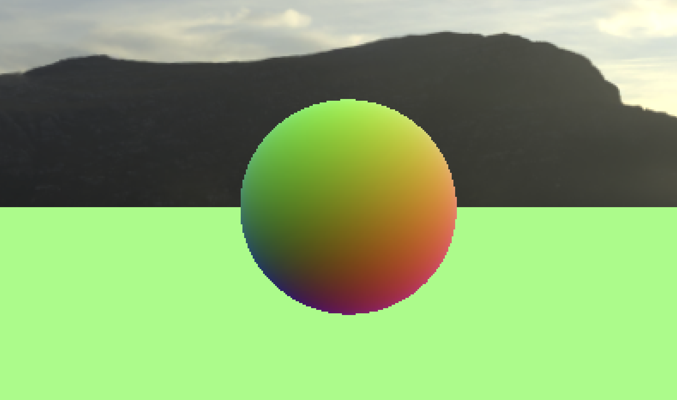
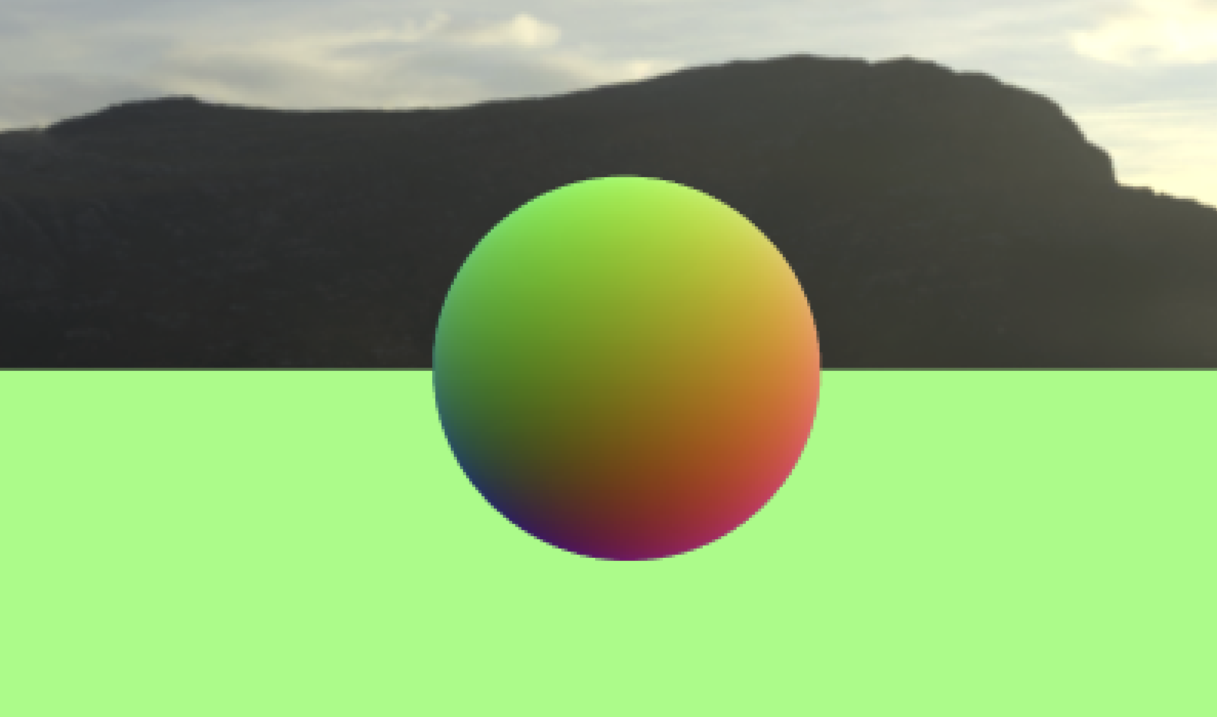
This yields a scene that looks like this:

All processed parallely on the GPU!
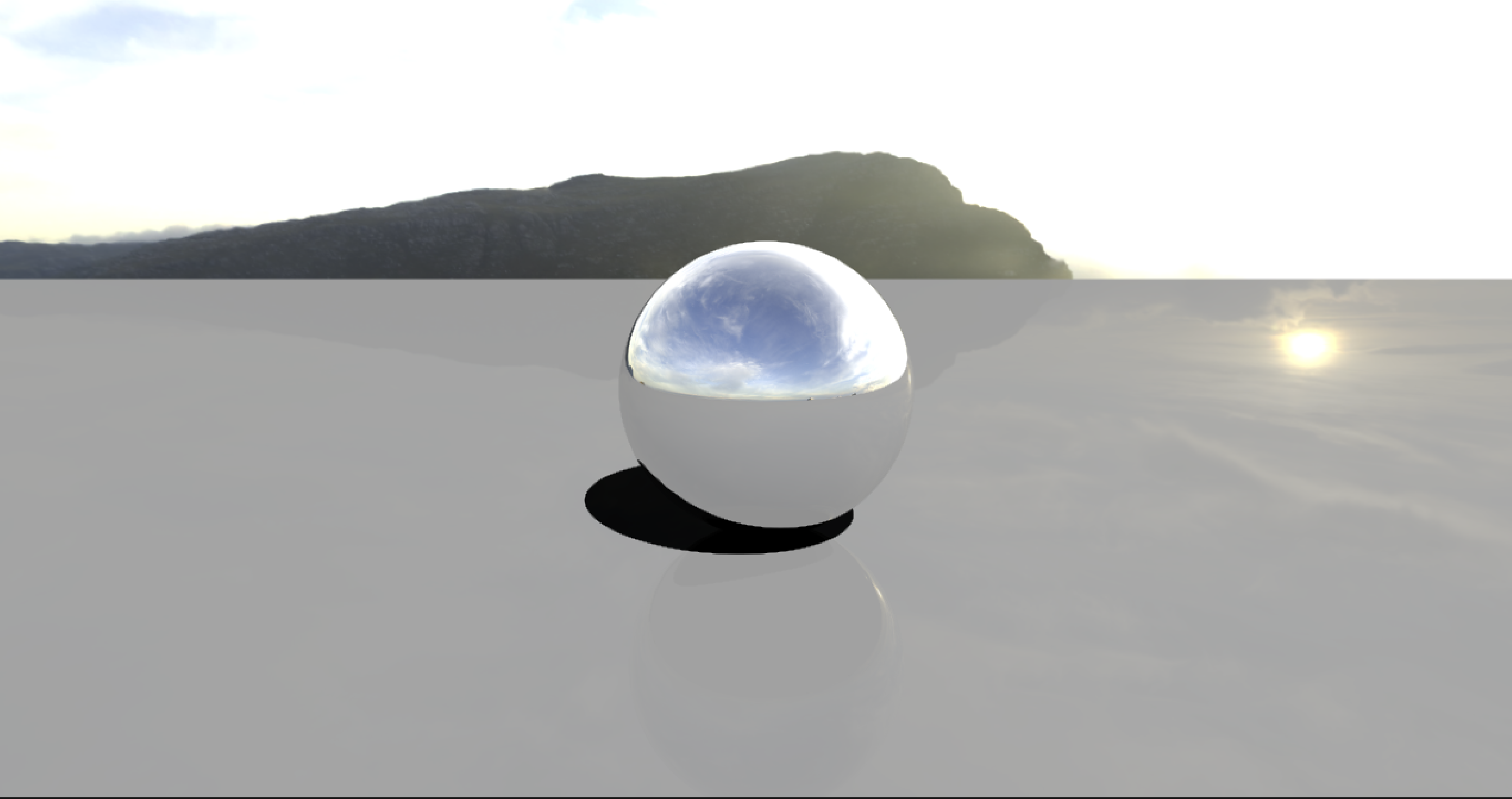
Skybox
Now, let’s implement a custom skybox (a texture for our sky). This can be accomplished by finding an asset that you like (in my example, I am using a picture of a hill), and assigning it to a texture in the inspector. Don’t forget to declare:
| |
and let the compute shader know about it:
| |
In the shader, let’s define the texture and a constant $\pi$ to help us sample the skybox and transform our cartesian direction vector to spherical coordinates and map this to texture coordinates. Fortunately, skybox sampling is a common technique in rendering, and we can simply use the following lines of code to correctly normalize and sample our texture in a sphere.
| |
Tracing
Here, we define a struct RayHit in our shader to help us render objects.
position and distance are simply the position and distance of a collision
relative to the camera. normal is the normal vector of a given ray and object
collision.
| |
Plane
Now, let’s add the ground plane. Here, we are creating a ground plane by finding the point of intersection between a ray and a plane at $y = 0$, then updating the bestHit given that the intersection is both positive and closer than all previous hits.
- We can think of finding the intersection as the following linear equation:
ray.direction.y * t + ray.origin.y = 0of the form $mx + b$.
| |
Note: HLSL parameters are passed by value, not reference. Thus, we must pass in
the RayHit with the inout qualifier to modify the original struct.
Otherwise, we would only be working on a copy and never propagate changes to the
calling function.
To use this, we will add a Trace function for each RayHit object, and a
basic shading function.
| |
Notice that we’ve moved the skybox sampling code into the shade function. Here,
we return the normal if the RayHit object encountered a collision, and
otherwise, use our skybox sampling code.
Now, we must use both functions in CSMain like the following:
| |
Sphere
To implement a basic sphere, we will use line-sphere intersection. There exist two possible collisions: the entry point and the exit point. We will use the entry point first and only use the exit point if the other one is not valid. Thus, a sphere can be defined as:
| |
To add a sphere, we will call this function from Trace like:
| |
Anti-Aliasing
Currently, we are only testing the center of each pixel with a single ray. This results in jagged edges due to a smaller number of samples. To circumvent this, we can trace multiple rays per pixel, with a random offset inside the pixel’s region. To reduce the computational load, we will trace one ray per pixel each frame and average the result over time if the camera didn’t move.
This can be fixed using an image effect shader written in Unity’s ShaderLab language:
| |
This is mostly default settings other than the lines:
| |
and
| |
which together enable alpha blending and draws sampels with a diminishing opacity. We will use this in our script by adding the following to utilize our samples and update changes to our camera.
| |
Adding our image shader to our Render function:
| |
Now, we need to create a random offset to sample in order to get the average gradient and smooth the jagged edges. In our compute shader, we can define the following:
| |
and replace our hard-coded float2(0.5f, 0.5f) offset with a random value:
| |
On the left, we see our result before the image shader. On the right, we see our result after the image shader. However, if you move the camera, we will still see aliasing for a couple of frames before it the texture has a chance to average out.
Reflection
In the real world, when light hits an object, different amount of protons bounce off the object depending on its material. Extremely reflective objects reflect most of the light and a majority of the energy in the proton is retained. Something else to remember from physics is that the incident angle is equal to the angel fo reflection. This will help us dictate how light bounces off objects in our render.
Let’s first tackle the problem of reflectivity. As light bounces from object to
object, the energy of the ray rapidly diminishes or the ray exits the scene.
This can be described with a float3 energy that we will add to the Ray
struct. The ray is initialized with float3(1.0f, 1.0f, 1.0f), or full
throughput on all color channels.
To make the energy of the ray diminish, let’s add the following to CSMain,
replacing our previous Trace and Shade calls:
| |
Now, our shade function will be responsible for both updating the energy and
generating the reflected ray. To update energy, we will perform an element-wise
multiplication with the specular color of the surface. For example, gold has a
specular reflectivity of roughly float3(1.0f, 0.78f, 0.24f), so it will
reflect 100% of red light, 78% of green light, and only 34% of blue light,
together creating a golden tint.
HLSL has a built-in function to reflect a ray using a given normal, so we can use the normal we’ve already declared. Our new shade function looks like:
| |
Notice that we add a slight offset to the normal direction. This is to fix floating point inaccuracy, as it is possible for a reflected ray to be blocked by the surface it is being reflected by.
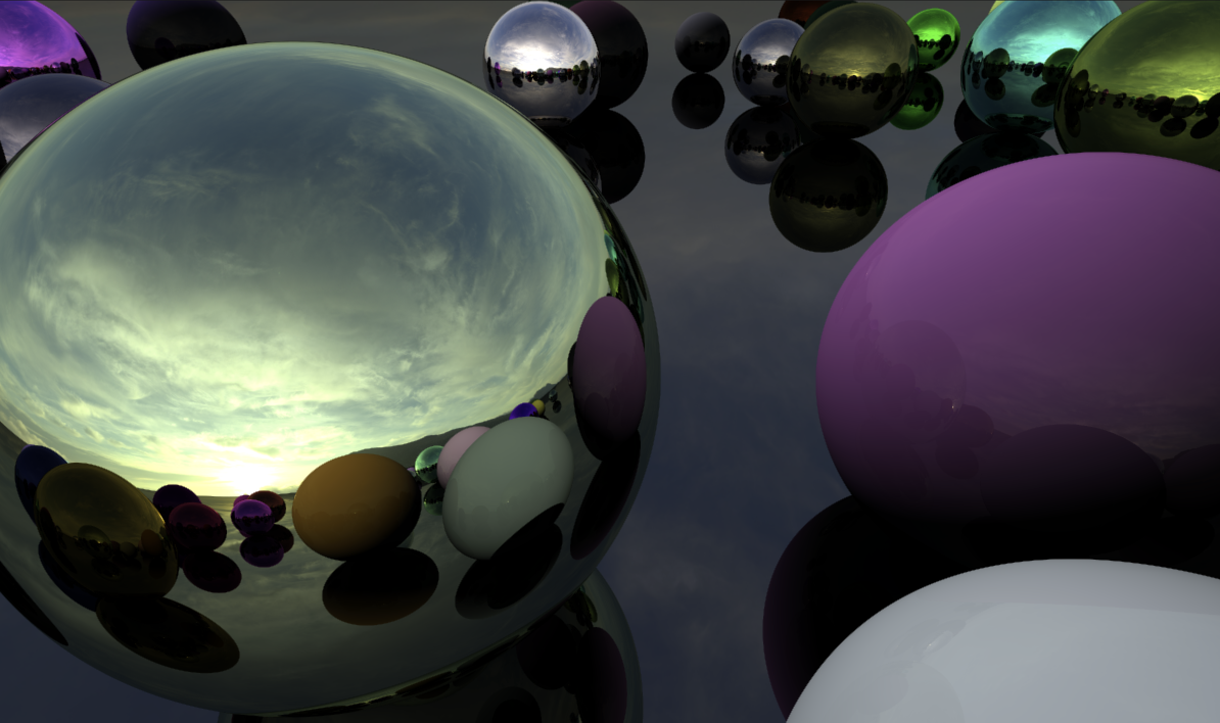
Here is the result of rendering some reflective spheres in a loop:
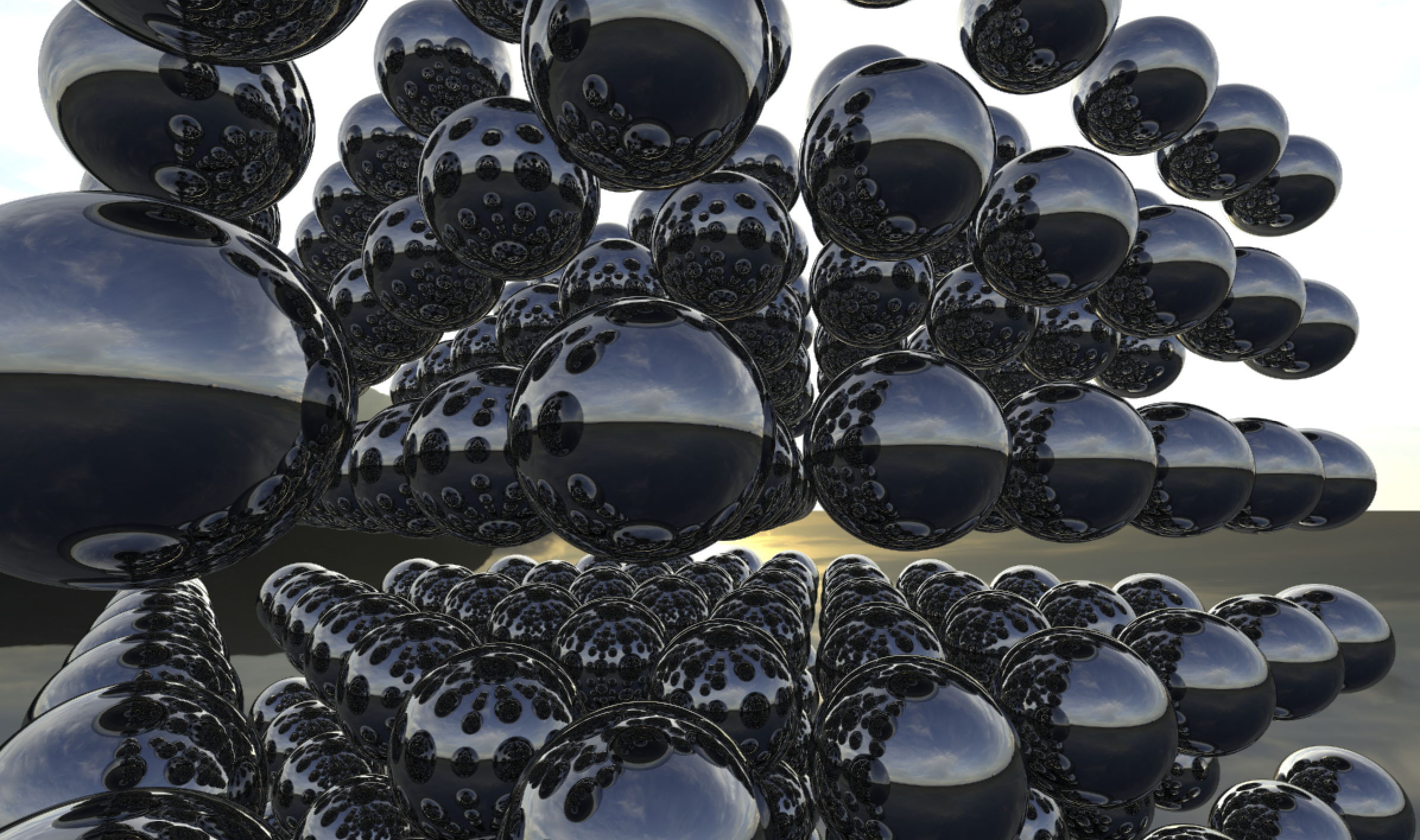
Directional Light and Materials
Let’s introduce two new properties of the RayHit struct in our shader,
float3 albedo and float3 specular. Specular reflection refers to highlights
caused by direct reflections of light sources. Adjusting this value will let us
adjust how much light is diffused into the surface normal, creating new
materials other than just the chrome finished spheres we have rendered. On the
other hand, albedo refers to the color of the surface when illuminated by a
light source. Together, adjusting these two values will allow us to simulate
many more surfaces in our ray tracer. This is called diffuse lighting, and the
topic is further discussed in this Stack Exchange post.
In order to implement these properties, let’s add the following to our compute shader:
| |
and the following to the C# script:
| |
Let’s update our SetShaderParameters fucntion to regonize our new directional
light vector each time we update our camera.
| |
We can now replace our simple black return with a simple diffuse shading:
| |
We take the dot product of the normal and the light direction and flip the direction to achieve our directional lighting. To cast shadows, we can first test the direction in which the light is coming from. Then, if anything blocks the way to infinity, we won’t use any diffuse light, creating the effect of a shadow. This can be accomplished by:
| |
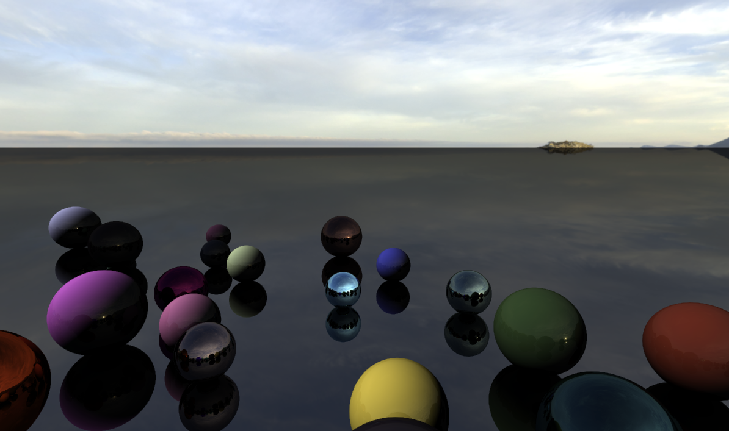
Now we can achieve simple glossy renders with shadows:
To take this a step further, we can define StructuredBuffer<Sphere> _Spheres.
This is where the CPU will store all spheres in the scene, allowing us to remove
our hard-coded spheres from the Trace function, and add the following:
| |
Since I’m running Unity on a Mac, I need to pass in the number of spheres to the compute shader beforehand, as the Metal API throws an error when passed a buffer with an unknown size. Simply pass:
| |
in the C# sharp script to let the compute shader know the size of our buffer.
Continuing, we can add some public parameters to control sphere placement and the buffer.
| |
Let’s setup our scene:
| |
We setup the scene in OnEnable, and release the buffer in OnDisable. The
SetUpScene function will try to position spheres in the provided radius, and
reject those that would intersect with spheres that already exist. Half of the
spheres will be metallic, and the other half will be non-metallic. 40
represents the byte size of one sphere in memory. Finally, we need to set the
buffer on the shader in SetShaderParameters like:
| |
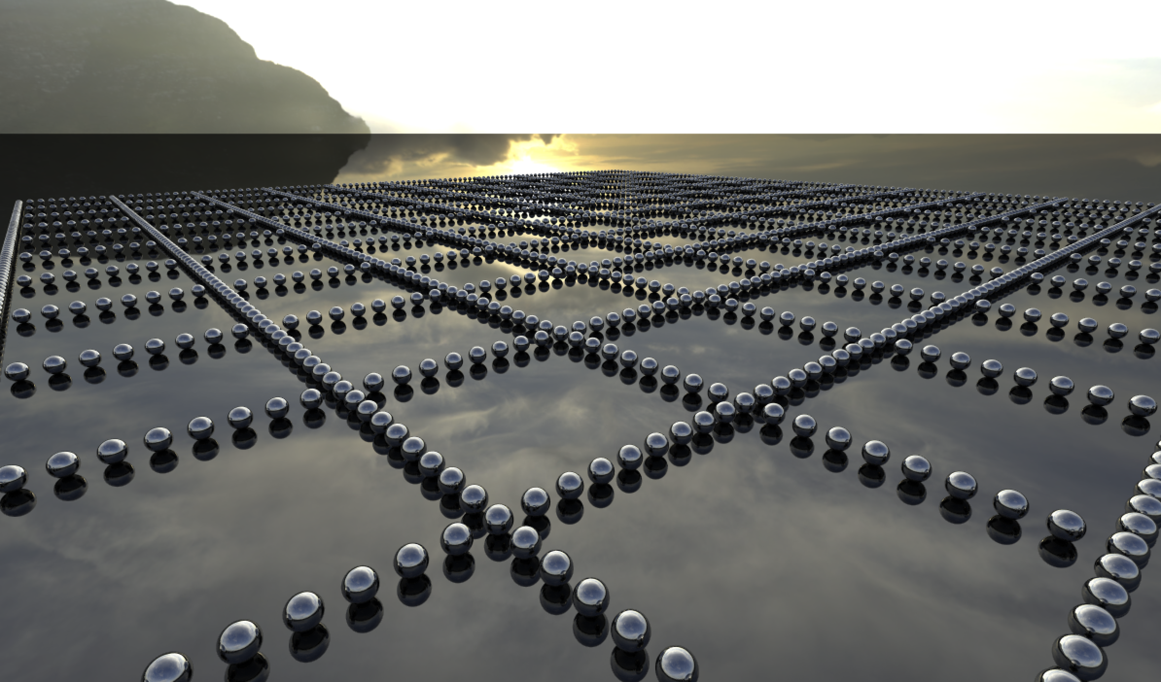
Our final product looks something like:
Conclusion
There are still many ray-tracing techniques to dive into, including illumination, using triangle meshes, and non-opaque materials. These topics and more may be covered in a future blog post.
As for now, the learning resources I used to get this setup include:
- Wikipedia
- Three Eyes Games
The source code for this blog can be found here.