Video Overview
Project Overview
Tasks
- Design our own hardware using verilog
- Design our own instruction set and assembler
- Successfully run three FEC programs
Restrictions
- Instructions can only be 9 bits long
- This limits the length of memory, number of operands, number of registers, the nature of J-type instructions, and more.
- Manual loop enrolling prohibited
- Separate instruction and data memory with a maximum size of $2^{10}$ entries.
- Single-ported data memory (one read/write per instruction) and same restrictions for registers
Programs
- Given a series of fifteen 11-bit message blocks in
datamem[0:29], generate the corresponding 16-bit encoded versions and store these indatamem[30:59]. - Given a series of 15 two-byte encoded data values – possibly corrupted – in data
mem[30:59], recover the original message and write into datamem[0:29]. - Given a continuous message string in
datamem[0:31]and a 5-bit pattern in bits [7:3] ofdatamem[32]:- Enter the total number of occurrences of the given 5-bit pattern in any byte into
datamem[33]. Do not cross byte boundaries for this count. - Write the number of bytes within which the pattern occurs into
datamem[34]. - Write the total number of times it occurs anywhere in the string into
datamem[35]. For this total count, consider the 32 bytes to comprise one continuous 256-bit message, such that the 5-bit pattern could span adjacent portions of two consecutive bytes.
- Enter the total number of occurrences of the given 5-bit pattern in any byte into
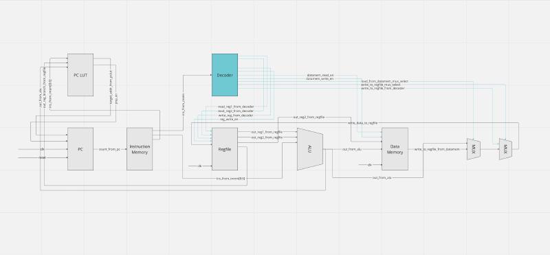
Architectural Overview
A detailed diagram of our architecture can be viewed here.
Hardware Implementation
Our top-level system verilog consists of the following structure:
| |
top_level.sv connects everything in components/ with clk, reset, and halt
wires connecting all the components to form the greater microprocessor.
program_tb.sv is the testbench that verifies the correctness of the program.
But before the program can be tested, we must first write our ISA and assembler.
The general debugging process of our hardware included analyzing the waveforms in Quartus, as can be briefly seen in the video.
Software Implementation
Given the limitations of the project, we designed our software in the following manner:
ISA
The below operations are the operations we deemed to be necessary and irreplaceable in our ISA:
| Operand | Type | Notes |
|---|---|---|
| NAND | R | Logical not and operation |
| LDR | R | Loads value from memory to register |
| STR | R | Stores value of register into memory |
| RSR | R | Rotates the value in R0 by R1 bits and moves the bits to the front |
| MOV | R | Moves the value of R1 into R0 |
| ADD | R | Adds the R1 and R0 |
| BNQ | R | Branches to the label operand if R1 and R0 are equal |
| SET | I | Sets the output register to the six input bits |
The outputs of all instructions are put into the OUT register.
The below operations can all be “emulated” using a series of NAND instructions
through the assembler. For these instructions, a register AI
or “arithmetic intermediate” was designated to handle intermediate operations
needed to achieve the desired result.
| Operand | Type | Notes |
|---|---|---|
| ORR | R | Logical or |
| XOR | R | Logical exclusive or |
| AND | R | Logical and |
For example, XOR r0 r1 can be emulated using:
| |
Assembler
Lastly, an assembler makes writing and debugging our programs much easier. Otherwise, our debugging process would be the following:
Read the lines of binary:
| |
Translate the binary to assembly, and proceed to diagnose the problem. This includes meticulously validating the correctness of each line of binary and only then diagnosing whether the issue stems from a logical error in the program or a deeper hardware issue.
As a result, we wrote an assembler in python to translate our custom ISA into
binary. The python script parses a .txt file, and spits out another .txt
with binary and the option to have it commented (for further debugging
purposes).
Here is an example code snippet from the assembler translating one XOR
instruction into 7 lines of NAND and MOV instructions:
| |
Conclusion
Our ISA and hardware ultimately correctly run all three programs. However, our program is by no means efficient. There are plenty of areas to improve including but not limited to: reducing clock cycle count through parallelization, identify and and short critical paths, and simplify the design.
If you would like to see the source code (verilog/python), I can show you upon request.